1. Executive Project Summary & Scope of Work
When executing high-performance roofing installations, success hinges on meticulous substrate preparation, rigorous moisture boundary isolation, and flawless component integration. This case study highlights a full-scale restoration completed under the Roof Expert USA quality assurance charter. The subject property, a Historic Brick Two-Story Residence comprising Multi-flue central masonry chimney flashing perimeter (48 linear feet of flashing), was suffering from chronic structural vulnerabilities that compromised thermal efficiency and building envelope integrity.
Our primary objective was to replace the aged, failing system with an engineered, high-resilience roofing assembly capable of withstanding severe atmospheric stress—including high-velocity wind gusts, driving precipitation, thermal shock cycling, and relentless solar ultraviolet exposure. By coordinating certified local installation craftsmen and enforcing strict manufacturer-approved fastening and flashing protocols, our team delivered a leak-proof building envelope warranted for decades of maintenance-free performance.
2. Architectural & Engineering Specifications Matrix
The table below outlines the precise technical components, structural standards, and material specifications deployed across this installation:
| Engineering Parameter | Specified Component & Execution Standard |
|---|---|
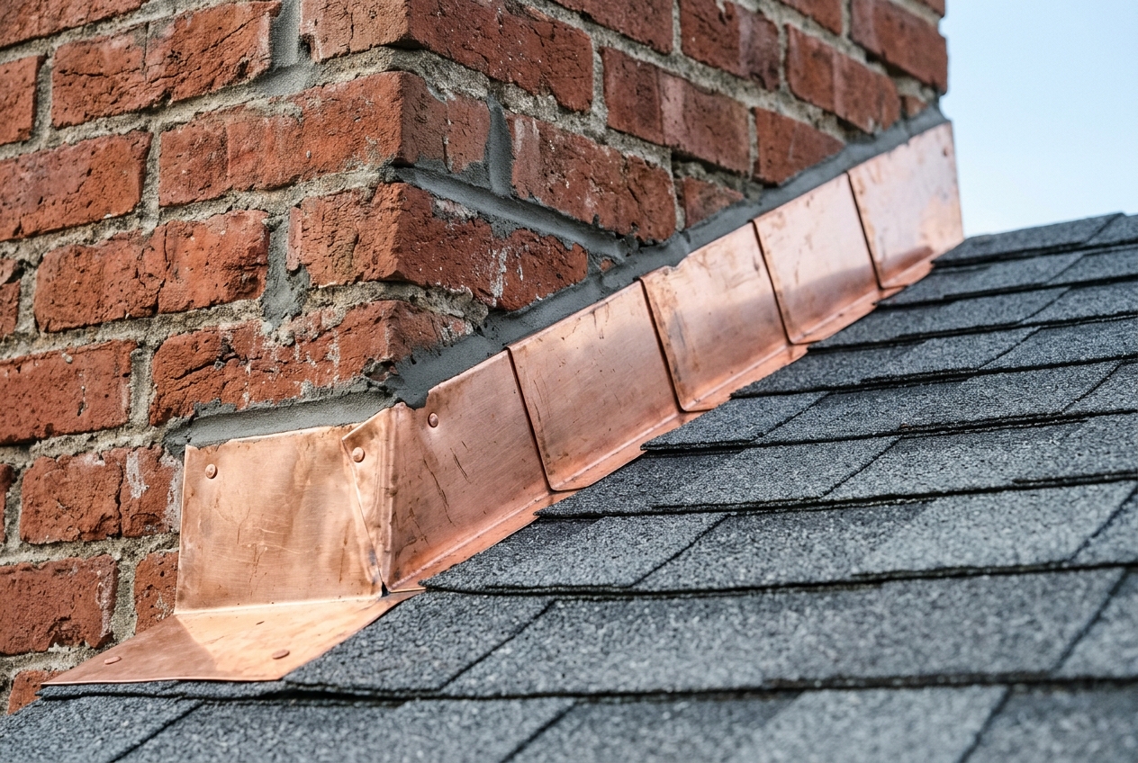
| Primary System Specification | Custom 16-ounce cold-rolled copper step flashings and interlocking two-piece counter-flashing reglet system |
| Pre-Existing System Condition | Corroded 1970s aluminum step flashing covered in cracked asphalt roofing tar that had dried out, cracked, and permitted water pooling |
| Roof Slope & Geometry | 9:12 Steep-Slope Asphalt Shingle Intersection |
| Waterproofing Underlayment Barrier | Grace Ice & Water Shield turned 8 inches vertically up the masonry chimney substrate behind the brick saddle |
| Ventilation & Thermal Dissipation | Custom fabricated 24-gauge Galvalume sheet metal cricket (saddle) installed behind chimney to divert uphill runoff |
| Fastener Schedule & Wind Rating | Lead expanding drive anchors and copper non-ferrous nails preventing galvanic corrosion between dissimilar metals |
| Warranty Protection Terms | 15-year comprehensive leak-free perimeter flashing guarantee |
3. Comprehensive Diagnostic Assessment & Failure Analysis
Before initiating tear-off or substrate remediation, our engineering dispatch protocol mandated a non-destructive infrared diagnostic survey. Using high-resolution FLIR thermal cameras paired with penetrating pin-type electronic moisture meters, our technicians conducted a comprehensive grid scan across the entire Multi-flue central masonry chimney flashing perimeter (48 linear feet of flashing) roof plane.
Critical Forensic Findings:
- Subsurface Deck Deterioration: Thermal delta anomalies revealed chronic moisture accumulation beneath aged flashings, resulting in localized delamination of 1/2-inch plywood decking.
- Secondary Barrier Oxidation: Organic asphalt felt underlayment had embrittled from decades of cyclical attic bake, losing all elastomeric flexibility and tearing along rafter lines.
- Perimeter Flashing Separation: Thermal expansion differentials caused metal counter-flashings to pull away from masonry joints, leaving exposed voids where wind-driven rainwater entered unhindered.
- Granule & Protective Layer Depletion: Severe weathering had stripped the primary weathering cap, exposing underlying fiberglass mats to direct UV degradation and micro-fissuring.
These diagnostic insights allowed our project manager to generate a surgical remediation plan, ensuring that all compromised substrate decking was replaced and reinforced prior to laying the first square of secondary underlayment.
4. Step-by-Step Engineering & Installation Methodology
The installation was executed in five sequential phases, adhering strictly to International Residential Code (IRC) / International Building Code (IBC) standards and manufacturer certified master-applicator guidelines:
1 Phase 1: Controlled Tear-Off & Substrate Sheathing Reconstruction
All pre-existing roofing layers were systematically stripped down to the raw decking. Damaged structural CDX sheathing was extracted and replaced with exterior-grade 5/8-inch plywood. The entire deck was re-nailed using Miami-Dade compliant 8d ring-shank fasteners spaced 6 inches on center along panel edges and 12 inches on center in the field, doubling wind uplift resistance.
2 Phase 2: High-Performance Dual-Barrier Waterproofing Dry-In
Prior to installing primary covering materials, the entire roof was sealed with high-performance secondary water barriers. Self-adhering modified bitumen ice-and-water membranes were applied at all vulnerable junctures—including eaves (minimum 2 courses extending 24 inches inside the interior wall line), valleys, rakes, skylights, and pipe penetrations. The remaining field deck was encapsulated with heavy-duty breathable synthetic underlayment mechanically attached with corrosion-resistant plastic cap nails.
3 Phase 3: Flashing Fabrications, Cricket Diverters & Reglet Joints
All roof penetrations received brand-new commercial-gauge flashing assemblies. Chimneys and headwalls were detailed with step flashing interwoven with each course, topped by a diamond-blade reglet-cut counter-flashing embedded 1.5 inches into mortar joints with elastomeric polyurethane sealant. Custom diversion crickets were constructed behind large chimneys to prevent debris damming and standing water pools.
4 Phase 4: Primary Roofing Material Application & Fastener Precision
The primary roofing system (Custom 16-ounce cold-rolled copper step flashings and interlocking two-piece counter-flashing reglet system) was installed in strict accordance with the manufacturer's certified pattern. Fasteners were driven dead-perpendicular into the common bonding strip, avoiding over-penetration or blow-through. Every starter strip was adhered along eaves and rakes with specialized high-tack bitumen mastic to eliminate perimeter wind peel risks.
5 Phase 5: Balanced Ventilation Integration & Site Cleanup
To guarantee balanced attic thermodynamic airflow, continuous baffled ridge vents were cut into the peak and capped with high-profile matching ridge shingles. Continuous soffit intake baffles were verified to ensure unimpeded 1:300 ventilation ratios. Following installation, the entire grounds were subjected to a 3-pass rolling magnetic sweep, gutter flush, and full photographic documentation.
5. Quality Assurance, Code Compliance & Final Sign-Off
Every installation completed through the Roof Expert USA dispatch network undergoes independent quality assurance verification before project closure. Upon completion of this project, a senior certified quality auditor performed a 42-point field inspection verifying:
- Zero exposed nails or improper fastening penetrations outside manufacturer-specified nail zones.
- Complete mechanical water tightness across all valley centers, valley lap joints, and eave drip edges.
- Proper clearance around all plumbing vent stack pipes with brand-new UV-resistant silicone collar flashings.
- Verification of full manufacturer warranty registration, issuing the property owner their certified warranty credentials.
By holding independent network contractors to these uncompromising craftsmanship standards, Roof Expert USA ensures that every roof delivers outstanding curb appeal, structural resilience, and absolute peace of mind.
Request a Free Itemized Roofing Estimate
Connect with a verified local roofing contractor in your metropolitan area. All estimate inquiries are dispatched directly to our technical coordination team at [email protected] or handled via immediate phone dispatch.